


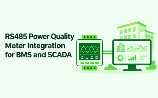
An RS485 power quality meter can deliver electrical data to a BMS, SCADA, PLC, or energy management system over a simple serial network. However, successful integration requires more than connecting two communication wires.
The installer must plan the bus topology, device addresses, baud rate, parity, termination, grounding, polling, and register mapping. A problem in any one of these areas can create missing values or unstable communication.
What Is an RS485 Power Quality Meter?
An RS485 power quality meter combines electrical measurement with an RS485 physical interface. In many projects, the device uses Modbus RTU over that interface.
However, RS485 and Modbus are not the same thing. RS485 defines the electrical communication layer. Modbus defines how devices exchange requests, responses, and data.
The Modbus Serial Line Protocol and Implementation Guide describes new serial implementations using an EIA/TIA-485 interface and a trunk network. Therefore, the physical bus and the application protocol must both match.
Typical RS485 Power Quality Meter Architecture
A common architecture is:
Power quality meters → RS485 Modbus RTU bus → PLC, BMS controller, SCADA server, or gateway → software
First, each meter measures the connected electrical circuit. Next, the controller polls selected registers. Finally, the upper-level software stores, trends, and displays the data.
A gateway may be useful when the upstream system needs Ethernet, Modbus TCP, MQTT, cloud connectivity, network separation, or local buffering.
Use a Bus Topology, Not a Star
RS485 normally works best as a daisy-chain or trunk. Devices connect along the main cable, while branch stubs remain short.
By contrast, a large star topology can create reflections and unstable communication. Therefore, avoid running a separate long cable from every meter back to one central point unless the network design uses suitable active equipment.
| Item | What to Confirm | Common Problem |
|---|---|---|
| Topology | Trunk or daisy-chain route | Long star branches |
| Address | Unique ID for every meter | Duplicate addresses |
| Serial settings | Baud rate, parity, stop bits | Devices use different settings |
| Polarity | Consistent A/B connection | Reversed pair |
| Termination | Applied at the correct bus ends | Missing or excessive termination |
Match Every Serial Setting
All devices on one bus must use compatible serial settings. Confirm:
- Device address
- Baud rate
- Parity
- Data bits
- Stop bits
- Response timeout
For example, a meter set to 9600 baud with even parity will not communicate correctly with a controller using a different format. In addition, two meters cannot share the same address on one bus.
Plan Polling Around Useful Data
A power quality meter may expose hundreds of registers. However, the BMS does not need to poll every value every second.
Therefore, group the data by purpose:
- Fast operating values: voltage, current, power, and frequency
- Medium-speed values: demand, power factor, THD, and unbalance
- Slow values: energy totals, maximum values, and configuration
- Event data: alarms, dips, swells, and records where supported
This approach reduces network load and improves response time. It also makes the BMS point list easier to maintain.
Confirm the Register Map Before Ordering
The product brochure may say Modbus RTU, but the integrator still needs the complete register map. It should define:
- Register addresses and function codes
- Data types and register length
- Signed or unsigned values
- Byte and word order
- Scaling factors and engineering units
- Read-only and writable registers
- Alarm and event access
- Firmware or protocol version
RS485 Power Quality Meter Options from Matismart
The Matismart PEM3000 supports RS485 Modbus RTU for BMS and SCADA integration. It provides three-phase electrical measurement, demand, unbalance, and harmonics up to the 50th order.
The PEM5000 fixed-panel meter adds deeper event, waveform, storage, and display functions. It supports both RS485 Modbus RTU and Ethernet Modbus TCP.
For several feeders, the MPM4000 combines multi-circuit measurement with RS485 and Ethernet communication.
Before final selection, confirm the exact registers, sensor inputs, wiring system, communication options, and firmware version required by the project.
RS485 Commissioning Checklist
- Verify voltage and current phase mapping
- Confirm CT ratio and sensor direction
- Assign a unique Modbus address
- Match baud rate, parity, and stop bits
- Check RS485 polarity
- Verify termination and cable shielding
- Read one known register
- Confirm scaling and byte order
- Compare readings with the meter display
- Document the final point list and settings
Frequently Asked Questions
Is RS485 the same as Modbus RTU?
No. RS485 is an electrical interface. Modbus RTU is a communication protocol that commonly runs over RS485.
How many power quality meters can connect to one RS485 bus?
The practical number depends on the transceivers, cable, distance, baud rate, polling load, and network design. Follow the device and controller limits rather than assuming one universal number.
Does an RS485 network need termination resistors?
Often yes, especially on longer or faster networks. Place termination according to the approved bus design and device documentation.
Can an RS485 power quality meter connect directly to a BMS?
Yes, if the BMS supports Modbus RTU and can map the meter registers. Otherwise, the project may need a gateway or controller.
Why does the meter display correct values while the BMS shows wrong values?
Common causes include an incorrect register address, data type, byte order, scaling factor, CT ratio, or phase mapping.
Treat Communication as Part of the Metering Design
An RS485 power quality meter is only useful when the upper-level system receives accurate and stable data. Plan the physical bus, serial settings, point list, and polling strategy before commissioning.
Share the meter quantity, cable distance, required data, BMS protocol, and system architecture with Matismart. Our team can help review the device and integration route.